![]()
|
Site home page Get alerts when Linktionary is updated Book updates and addendums
Get info about the Encyclopedia of Networking and Telecommunicatons, 3rd edition (2001)
Download the electronic version of the Encyclopedia of Networking, 2nd edition (1996). It's free! Contribute to this site Electronic licensing info
|
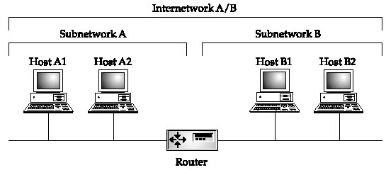
IP (Internet Protocol) Related Entries Web Links New/Updated Information Note: Many topics at this site are reduced versions of the text in "The Encyclopedia of Networking and Telecommunications." Search results will not be as extensive as a search of the book's CD-ROM. The Internet Protocol (IP) is the internetworking protocol for the Internet and enterprise intranets. IP is a network layer protocol that provides datagram services for transport layer protocols such as TCP and UDP. See "TCP (Transmission Control Protocol)" and "UDP (User Datagram Protocol)" for separate coverage of those protocols. This site refers to the Internet Protocol suite as simply "TCP/IP," even though IP is a subset of the Internet protocols. See "Internet Protocol Suite" for a general overview of the entire set of Internet protocols and historical information about the development of those protocols. As a network layer protocol, IP provides datagrams routing services. Datagrams are the packets that carry user and application data end to end across router-connected networks. Routing topics are discussed under "Routing" and "Routers." In addition, the topic "Routing on the Internet" provides a historical overview of the development of routing on the Internet. This section discusses IP version 4 in general and the unicast nature of IP (sending datagrams from one host to another host). Multicast IP is a one-to-many transmission scheme and it is discussed under "Multicasting." IP is defined in RFC 791 (Internet Protocol, September 1981). This RFC was later amended by many additional proposals and updates. Internetworking An internetwork consists of individual networks joined by routers, as pictured in Figure 1. Networks A and B are connected to create internetwork A/B (I'm using this terminology to simplify the discussion up front).
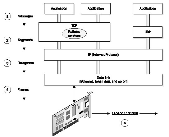
Figure 1: IP is a communication protocol that supports interconnected networks with a global addressing scheme The Internet is a collection of networks called autonomous systems (ASes). Each AS is managed by different authorities and contains its own internal network of routers and subnetworks. An AS is connected to other ASes via gateway routers and external connections. It may be directly connected to other ASes or go through Internet exchange points. This architecture is outlined in more detail under "Internet Architecture and Backbone." Each AS has its own IP network address or range of IP network addresses. Routers are like traffic cops at the network interconnection point. They know the IP network addresses of connected networks and forward packets appropriately. Every computer on the Internet must have a unique address. IP supports unique addresses by way of a hierarchical addressing scheme. An IP address is a unique number that contains two parts: a network address and host address. The network address is used when forwarding packets across interconnected networks. It defines the destination network, and routers along the way know how to forward the packet based on the network address. When the packet arrives at the destination network, the host portion of the IP address identifies the destination host. Think of IP as an "overlay" addressing scheme for interconnected networks. The U.S. ZIP code is a sort of overlay addressing scheme. A zip code identifies a specific city (or area within a city), much like the network portion of the IP address identifies a specific network in a group of interconnected networks. Also, the street address on an envelope defines the destination for a letter, much like the host portion of the IP address identifies the destination computer. A design goal of the early Internet was to create a very basic network connectivity model that would provide fast and efficient data exchange among distributed systems without restrictions on the host systems. If applications needed additional communication services, those services would be provided by end systems and not by the network itself. In fact, the Internet protocols will work on just about any type of underlying network technology, including Ethernet, wireless, and optical. As shown in Figure 2, TCP and UDP are layered on top of IP and take advantage of IP's datagram delivery services. TCP is a transport layer end-to-end protocol that provides a set of reliable data delivery services not provided by IP. If an application does not need TCP's services, it goes through UDP.
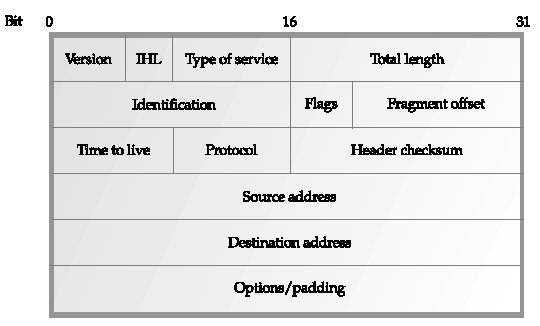
Figure 2. The TCP/IP protocol stack in relation to applications and the network Applications make calls to TCP or UDP for network services. Application data or messages are encapsulated in TCP segments or UDP datagrams and then passed down to IP. IP passes datagrams down to the underlying network, which frames the data into "blocks" for transmission across the local network medium. The interaction between protocol layers is discussed further under "Network Architecture." Some applications, like file transfers, require absolute guarantees that TCP provides in delivering packets. It takes time and additional resources to signal that a packet must be retransmitted, but the delay is worth it to ensure data integrity. In contrast, real-time voice doesn't need an absolute guarantee that every packet is delivered. Trying to retransmit a lost packet in a live data stream disrupts the flow of on-time packets. Therefore, streaming multimedia applications use UDP. Services offered by TCP are covered under the TCP topic and under "Transport Protocols and Services." For information about services that support real-time and streaming applications, see "Multimedia." The Internet has a characteristic that its designers and engineers refer to as transparency. Transparency is the concept of a single universal logical addressing scheme and the ability of packets to flow from source to destination (end-to-end) essentially unaltered. This is discussed in RFC 2775 (Internet Transparency, February 2000). More recently, end-to-end transparency has been lost due to the deployment of NATs (network address translation devices) as well as firewalls, proxies, and caches. These devices cause problems for many Internet applications that require stable and continuous IP addresses. In such cases, custom application-level gateways are required to perform translation for those applications, but even then, end-to-end transparency may not be restored. IPSec is affected by NATs. It uses cryptographic functions for authentication, integrity, and confidentiality. The problem is that it encrypts the header and/or payload of packets which can prevent NATs from doing their job. Refer to the NAT and IPSec topics for more information. Internetwork Routing Routers interconnect different networks. Each network has its own IP network address. When a packet arrives at a router, it determines the best way to forward that packet (i.e., which output port to use). However, routers only need to determine the next best hop toward a destination, not the complete path to the destination. This is like getting directions while walking in a city. A person may point you in the right direction at an intersection. At the next intersection, another person points you in the right direction. Eventually, you get to where you want to go-not by knowing the exact path from the start, but by being pointed along the way as you go. This is discussed further under "Routing." At one time, routers were called gateways because they provided a path or connection into another network. The term is still used to specify which router on the network serves as a gateway to another network. For example, assume an enterprise LAN is connected by one router to another enterprise LAN and by another router to the Internet. When configuring an Internet connection, the Internet-connected router is specified as the primary Internet gateway. See "Routers" and "Routing" for more information. Also see RFC 1812 (Requirements for IP Version 4 Routers, June 1995). IP Datagram IP datagrams are the "envelopes" that carry data across IP networks. Datagrams are assembled by the source computer and sent out on the network. Routers transfer the datagram from one network to another. To traverse a particular network, datagrams are encapsulated within the frames of that network. However, not all networks have the same frame size, so a datagram that fits nicely in a single frame on one network may need to be fragmented and carried in multiple frames on another network. Routers handle this job. Each network has its own MTU (maximum transmission unit), which is the maximum size for an IP datagram. See "Fragmentation and Reassembly" for more on this. The IP datagram header is pictured in Figure 3. Data of variable length is attached directly after the header. The maximum length of the datagram including header and data cannot exceed 65,535 bytes. Also note that the datagram aligns on 32-bit boundaries.
Figure IP-3: IP datagram The datagram fields are described in the following list:
IP Addressing and Host Names The previous discussion describes how IP delivers datagrams over router-connected networks. This section describes the other important component of IP: the addressing scheme. In reality, there are multiple addressing and naming schemes in use on a typical IP network at any one time. For example, there are host naming schemes (as opposed to numbering schemes) that allow humans to refer to computers with easy-to-remember names. The Internet's DNS (Domain Name Service) provides a service that translates names into IP addresses. Refer to "DNS (Domain Name Service)" for more information about Internet naming schemes. There is also the IP addressing scheme, which consists of both a network identifier and a host identifier. And then there is MAC addressing, which identifies computers via the hardwired address built into network interface cards. Keep in mind that IP host addressing is a network layer function that identifies a specific computer across an internetwork. It is part of IP's "overlay" internetwork addressing scheme. MAC addressing is a data link layer function that operates within LAN boundaries (i.e., a specific broadcast domain). When a packet arrives at a router, the router translates the destination host's IP address into a MAC address, then puts the data in frames that are addressed to the host with that particular MAC address. The IP address scheme is discussed in RFC 791 and the following RFCs. Also refer to "Internet Organizations and Committees" and "Registries on the Internet" for more information about the organizations and techniques for allocation IP addresses on the Internet.
IP Address Structure An IP address is a 32-bit binary number that contains two separate pieces of information:
While computers work with IP addresses as 32-bit binary values, humans normally use the dotted-decimal notation. A binary address and its dotted-decimal equivalent are shown below. Note that the 32-bit address is divided into four 8-bit fields called octets. 11000000.10101000.00001010.00000101 = 192.168.10.5 You can pull out your binary-to-decimal calculator to do these conversions (if you run Windows, open the Calculator and choose Scientific on the View menu). For example, type in 192, then convert it to binary to get 11000000. It is common to refer to the four 8-bit fields as follows for simplicity: w.x.y.z Using this abbreviated form makes it easier to discuss the different addressing schemes without having to show the full set of binary digits when they are not necessary to the discussion. For example, if only the right-most eight bits are essential to the discussion, then i'll use a notation similar to "w.x.y.00000101." IP Address Classes In the early days of the Internet, the 32-bit IP address space was allocated into three address classes: class A, class B, and class C. As discussed later, the class system would be all but phased out by now except that so many organizations "own" class-based blocks of addresses and many will not voluntarily give them up. Also, the changeover has been difficult. Keep in mind that the address is split, with the left part indicating the network and the right part indicated a host. The question is, where does the network part end and the host part begin? It varies depending on which class of network address you are referring to. The three classes are outlined below. The important thing to notice is that each class support a specific number of networks and a specific number of hosts on each of those networks.
The IP address classes are pictured in Figure 4 and described below. Keep in mind that you are assigned an IP address by an Internet organization or service provider, based on your needs (number of hosts) and the address range that is available. The address you are assigned is just the network identifier portion. You are responsible for assigning addresses to individual hosts within your network. As discussed later, you can also use subnetting techniques to subdivide a given range of addresses.
Figure 4: IP address classes
A class D scheme also exists for multicasting. The first 4 bits (1110) identify the class, and the remaining 28 bits refer to a group of hosts, all of which receive the same IP packet. Refer to "Multicasting." A class E was also defined for future use, with the first four bits being 1111. There are some guidelines for working with network and host numbers:
Private IP Addresses A private IP addressing scheme allows an organization to use any IP internal addressing scheme (class and subnetting scheme) that fits it requirements. Any devices connected directly to the Internet (Web servers, e-mail servers, etc.) require a public IP network address, which can be obtained from a network registrar. A proxy server or NAT (network address translation) server separates the internal and external networks and acts as a "gateway" between them. What these servers do is intercept outgoing packets and change the private IP address to a public IP address. When a response to the packets comes back, the servers convert the public IP address back to the appropriate private IP address. Lookup tables are maintained, while an internal host maintains an external session. A pool of public IP addresses is kept on hand for use in the translation. This pool does not need to equal the number of internal hosts, assuming that all of those hosts don't access the Internet at the same time. See "Proxy Servers" and "NAT (Network Address Translation)" for more information. Private IP addresses help to hide internal hosts addresses from potential hackers. In addition, you have the freedom to create any networking scheme you need instead of being tied to an Internet-assigned scheme. Three address blocks were reserved for private use as defined in RFC 1918 (Address Allocation for Private Internets, February 1996). These addresses are never used on the public Internet and are not even accessible across routers. A host on one of these private addresses must go through a proxy server or NAT to access the Internet:
The Subnet Mask A subnet mask is an IP address feature that serves as a sort of template to indicate which bits in the IP address define the network and which bits define the host. All devices on the same IP network must use the same subnet mask. The subnet mask became necessary when subnetting procedures (described next) were developed for IP addresses. The standard subnet masks used for the class A, B, and C networks are shown in the following table, along with the binary equivalent:
Note how the binary 1s indicate the bits that are used for the network address portion of the IP address. They essentially "mask out" the network address to reveal the host address. As an example, a class B address of 128.10.50.25 and a class B subnet mask of 255.255.0.0 are shown in the following table. The mask indicates that the first two bytes are the network address, so the last two bytes are the host address.
Subnetting A subnet is a logical subsection of an IP network. You create subnets to separate groups of hosts for security reasons, for traffic control purposes, or other reasons. Subnets are usually created within enterprise networks to create departmental networks. A service provider with a large block of IP addresses creates subnets so that it can allocate blocks of IP addresses to subscribers. Just like networks on the Internet, routers are required at subnet boundaries to transmit packets from one subnet to another. In terms of addressing, subnetting is equivalent to adding a third level to the Internet addressing hierarchy. The normal levels include all the networks of the Internet and then the hosts on those networks. Subnetting creates a sublevel of networks within each network. An enterprise or an ISP may configure subnetting to divide a large network into two or more smaller networks that are easier to manage and that match the physical and transmission requirements of the underlying networks. Subnetting is discussed in RFC 917 (Internet subnets, October 1984), RFC 932 (Subnetwork addressing scheme, January 1985), RFC 950 (Internet Standard Subnetting Procedure, August 1985), and RFC 1219 (On the assignment of subnet numbers, April 1991). For example, a class A addressing scheme provides over 16 million host addresses for a single network. But a single network that uses even 1/100 of 1 percent of those addresses would be too large to meet the specifications of most LANs. The specifications for Ethernet allow only 1,024 nodes per network. In additional, there are electrical parameters and cable length limitations. Most important, the broadcast nature of LANs like Ethernet makes it impossible to support a large number of hosts at the same time. Ethernet networks are shared media systems. When a host wants to transmit, it checks to make sure no other host is transmitting. If there are thousands of computers on the network, a computer may never get a chance to transmit. In addition, multiple computers will still attempt to transmit at the same time, especially if the network is so large that it is hard to detect that a distant node has begun transmitting. Busy Ethernet networks may exhibit performance problems with as few as 50 hosts. So the basic problem is that you have one IP network address, but you need to subdivide your network into multiple interconnected networks for management or performance reasons. One way to do this is to obtain additional IP address blocks from service providers. A better choice is to use private network addressing, then install a proxy server or NAT between the internal network and the Internet. This latter method gives you the freedom to use any addressing scheme that fits your needs. But subnetting will be necessary if you are working with a legacy network that already uses Internet-compatible addresses, or if you plan to connect the network to the Internet and you only want to have one public IP address. In this case, subnetting is all about conserving and making the best use of the available address space. That means subdividing the address space into multiple networks, each with enough host addresses to fit your needs. However, as you will see, dividing the address spaces involves making trade-offs between the number of networks and the number of hosts. Note that this section discusses static subnetting, in which the same subnet mask is used over the entire network of subnets. Variable-length subnetting allows different subnet masks, as discussed in the next section. Assume you have one large Ethernet network with 1,000 hosts and a single class B network address. The network is saturated and you must subdivide it into separate broadcast domains to contain traffic and to separate users into departments and workgroups. Subnetting lets you create hundreds or even thousands of individual networks out of the class B address. You then need routers to interconnect the new subnetworks. Routers forward messages to the proper subnet by evaluating the subnet mask. The key to subnetting is to use some of the host bits for the subnet address. The two-part IP address becomes a three-part IP address as shown here: <network identifier> <subnet identifier> <host identifier> The subnet identifier must be at least 1 bit. A 1-bit value means that only two subnets exist (either the bit is 0 or 1). If the subnet identifier is two bits, then four subnets are possible (00, 01, 10, 11). Assume you are using the IP network address 192.168.0.0. The bit pattern for this address is: 11000000.10101000.00000000.00000000 To subnet this address, you use one or more of the host bits, depending on how many subnetworks are needed. In Table 1, the underlined bits in the third octet (the y octet) are used for subnetting. A 3-bit value provides eight possible decimal numbers as shown, giving eight subnets (subnets 0, 32, 64, 96, etc.). If you're confused about the binary/decimal relationship, pull out your binary to decimal calculator and you'll see, for example, that "01000000" converts to "64" and vice versa.
Table 1: Using 3 bits for subnetting The /19 notation is a shorthand technique to indicate that the 19 leftmost bits are the network address. This notation is usually used in place of specifying the entire 32-bit binary subnet mask, as explained below. The actual range of host IP addresses that can be derived out of the class B network address in Table I-1 (with three bits used for subnetting) is outlined in Table I-2.
Table 2: Address Ranges for eight Subnets RFC 1878 (Variable Length Subnet Table For IPv4, December 1995) provides subnet tables, as well as network IDs, host ranges, and IP broadcast addresses with emphasis on Class c subnets. Tables I-3 shows how subnetting works in terms of the subnet mask for class C addressing.
Table 3: Subnetting for class C addressing In the second column, you can see that as you increase the bit width of the subnet identifier field (the 1s), you decrease the size of the host identifier field (the 0s), thus reducing the number of host you can have on each subnet. For example, if you use four bits to subnet a class C address, you can create 16 subnetworks. But that only leaves four bits for the host address, meaning that only 14 hosts may exist on each subnetwork. Keep in mind that all 0s and 1s are reserved for the network identifier and broadcast address respectively. To subnet an IP address, you first need to get an idea of the number of networks you need and the number of hosts to be connected to each network, now and in the future. The fourth and fifth column in Tables I-3 show the number of subnets and hosts per subnet. As mentioned, you can use subnet notation in place of using the entire 32-bit subnet mask. The notation is listed in the third column of Table 3. Also, only RIP v2 or the OSPF routing protocol fully support subnetting. For more information about subnetting, refer to the following Web sites:
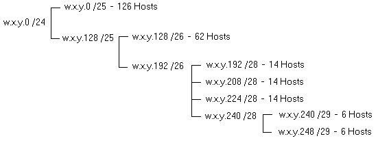
Variable-Length Subnetting Subnetting can be taken one step further. As mentioned previously, basic subnetting requires that you find a subnet value that provides a balance between the number of subnets you need and the number of hosts on each of those subnets. For example, for a class C network, you might choose a 3-bit subnet mask to obtain eight networks with up to 30 hosts each. But assume you have one network with 50 hosts and six networks with 10 or fewer hosts. Which subnet scheme do you use? In fact, there is no class C configuration that satisfies this requirement. Variable-length subnetting solves this problem by eliminating the "one configuration must fit all" restriction of standard subnetting. It is defined in RFC 1878 (Variable Length Subnet Table For IPv4, December 1995). Variable-length subnetting and CIDR (discussed next) move away from the classful interpretation of addresses as has been discussed in the previous sections. Classful interpretation is being able to determine the class of an address (A, B, C, D, E) and the subnet mask to use by looking at the first few bits in the address (class A = 0, class B = 10, and class C = 110). Basically, variable-length subnetting involves "subnetting the subnets." First, you subnet the existing address space into top-level subnetworks, then you subnet those networks into yet smaller subnets to fit your needs. Those subnetworks can also be subnetted. The final address space will be hierarchical. Figure 5 and Table 4 show how a class C network address is "sub-subnetted."
Figure 5: Variable-length subnettings creates subnet hierarchy
Table 4: Variable Subnetting for Class C Network This hierarchy has the advantage of aggregating the network address space so that routers at the top of the hierarchy do not need to maintain routing information for all of the subnetworks. A packet passing through the top-level router will be routed within the subnetted hierarchy. CIDR (Classless Interdomain Routing) and Supernetting Just as an organization can use variable-length subnetting to divide its network into multiple subnets, CIDR (pronounced "cider") provides a way for ISPs to subdivide their address blocks into pieces that fit the size of their customers. CIDR employs address aggregation, in which multiple contiguous blocks of addresses are referred to by the network number they have in common. In addition, subnetting presents an organization's network address to the outside world as a single address while allowing multiple internal networks. CIDR also provides this capability for ISPs. The rest of the Internet sees only a single network address for the block of addresses it has been assigned. Internally, the ISP is subdividing the address and routing packets appropriately. This has great benefit for the Internet routing tables because only a single entry is needed for an ISP's network. The ISP's routers then handle all routing within its network. See "OSPF (Open Shortest Path First)" for information about interior routing. See "BGP (Border Gateway Protocol)" for information about exterior routing. While many organizations typically deal with class C-size network addresses, in the past ISPs have been assigned class A or class B network address, or multiple class B and class C addresses. Some ISPs allocate part of their address space to lower-level ISPs, and those lower-level ISPs may allocate parts of their address space to other ISPs or organizations. The important point is that addresses are allocated as a contiguous block that are aggregated and advertised to the outside world as a single IP network address. This single network address is all that the higher-level ISP needs to know about. In turn, this ISP has an aggregation of addresses that it advertises as a single network address to even higher-level ISPs or backbone routers. Historically, supernetting was first discussed in RFC 1338 (Supernetting: an Address Assignment and Aggregation Strategy, June 1992), which was later replaced with RFC 1519 (Classless Inter-Domain Routing: an Address Assignment and Aggregation Strategy, September 1993). According to Tim Bass in a paper about exterior routing protocols (see link of related entries page): RFC 1338 was a major paradigm shift to establish a provider-based addressing and routing hierarchy. With the new RFC 1338-style provider-based supernetting, it was possible to create multiple hierarchical tiers and most tiers were envisioned to be IP service providers. Provider-based address space allocation was the new model, and BGP would evolve to BGP-4, incorporating the RFC 1338 paradigm. For this shift to occur, the technique for Supernetting-subnetting the IP address space required a modification. This new feature was called Classless Inter-Domain Routing. (Note that RFC 1338 was replaced by RFC 1519). For more information, refer to "CIDR (Classless Interdomain Routing)" Also refer to RFC 1787 (Routing in a Multi-provider Internet, April 1995), RFC 2008 (Implications of Various Address Allocation Policies for Internet Routing, October 1996), RFC 2519 (A Framework for Inter-Domain Route Aggregation, February 1999), and RFC 2050 (Internet Registry IP Allocation Guidelines, November 1996). RSIP (Realm-Specific Internet Protocol) A proposed Internet protocol called RSIP (Realm-Specific Internet Protocol) solves some of the address problems of IPv4, and provides better support for multimedia. The IETF has stated that RSIP is a replacement for NAT (network address translation) and a potential alternative to IPv6. At the same time, RSIP provides a transition path to IPv6 for organizations that implement it. NAT has some shortcomings, such as its inability to work with the IPSec (IP Security) protocol and the inability to establish TCP peer-to-peer connections. A NAT translates an internal address into an address that can be used on the Internet, effectively hiding internal addresses. Thus, an organization does not need an Internet-compatible IP address for all its internal hosts, which saves Internet addresses. However, IPSec requires that the same IP address be used from host to host and not be converted by some device in between. RSIP solves this problem by allowing routers to support host-to-host IPSec sessions. RSIP was still in draft form at the time of this writing. 3Com developed the protocol in early 1998. It is undergoing development and modifications and may emerge with many changes by the time you read this. Refer to RSIP (Realm-Specific Internet Protocol) for more information. IPv6 (Internet Protocol version 6) IPv4 has served the Internet community well, but its limited address space has caused problems. The use of private network addressing and NATs, as well as the development of CIDR, has helped to resolve some of these address limitations and security problems, but they are considered temporary fixes. The next generation of the IP protocol is IPv6, which was designed to resolve most of the problem inherent in IPv4. IPv6 was officially deployed in 1999, but the Internet community has failed to make the complex transition, even though IPv6 features are sorely needed. The IETF began working on a next-generation IP protocol in 1990. One of the original formulations of the proposals for a next-generation IP protocol was outlined in RFC 1752 (The Recommendation for the IP Next Generation Protocol, January 1995) and RFC 1753 (IPng Technical Requirements, December 1994). The current best document is RFC 2460 (Internet Protocol, Version 6 Specification, December 1998). RFC 3056 (Connection of IPv6 Domains via IPv4 Clouds, February 2001) describes the interim mechanism for IPv6 sites to communicate with each other over the IPv4 network without explicit tunnel setup. The two IETF working groups mentioned below have more information on IPv6 and list all the relevant drafts and RFCs. The 6Bone is a testbed for IPv6 that helps vendors and users participate in the actual evolution and transition to IPv6. The other Web sites listed below provide additional information:
The most important feature of IPv6 is its longer 128-bit address space, compared to 16 bits for IPv4! While IPv4 is limited to four billion addresses (many of which are wasted due to class-based addressing), IPv6 supports 3.4 × 1038 addresses, which reportedly allows for 50,000 addresses for every square meter of land on Earth. While this number may seem high, many billions of addresses will be needed in the future to provide unique addresses for every person and device on the planet. IP addresses will be needed for the explosion in mobile wireless devices and embedded systems contained within everything from home entertainment systems to automobiles to alarm clocks. Most people will own multiple devices that each require a unique IP address. In addition, mobile users can have a temporary second address called the "care-of" address where messages are automatically forwarded if the user is not at their primary address. IPv6 contains many built-in features, as opposed to be added-on features, as was the case with IPv4. These include the following:
There are many other changes in IPv6 when compared to IPv4. Full implementation of IPv6 is years away, and there is some doubt that the switchover can ever be pulled off. However, vendors like Cisco are advocating a gradual switchover to IPv6, rather than a "flag-day" in which the entire Internet is converted. Dual protocol stacks (IPv4 and IPv6) are being implemented in devices all over the Internet to support the changeover. MPLS may also provide some help in the transition. With MPLS, packets are forwarded based on labels instead of IP header information. Therefore, IPv6 packets can be transported across core networks that do not natively support IPv6. Network World Magazine printed an interview with Internet pioneer Vint Cerf in its October 25, 1999 issue with the headline "Internet Pioneer: IPv6 Transition Needed." Cerf was concerned about running out of address spaces and the "ugly" use of NAT boxes. He mentions that "a state of denial exists among some ISPs, who would just as soon not face this problem," and that "if anybody should be paying attention to this, it's the ISPs. Most of them are betting the farm on NAT boxes in the near term." NAT boxes can provide a temporary solution that accommodates both IPv4 and IPv6, but the address problem won't go away and there are serious problems with using NATs, as discussed under the NAT heading. IPv6's large address space is considered crucial as more and more wireless devices, mobile devices, and embedded systems emerge, and as millions of new users all over the world come online. Copyright (c) 2001 Tom Sheldon and Big Sur Multimedia.
|